· Some of the worksheets below are Free Electricity and Circuits Worksheets : Definitions of What is Electricity?, What are circuits?, Open vs closed circuit, Circuit elements – Switches, Resistors, Capacitors, Inductors, Transistors, Resistors, ., Electricity Unit : Class notes – Atoms, Electrical charge, Electrical current, Electrical circuit, Types of electrical circuit, Conductors of ...
How to Draw Electrical Diagrams. Making wiring or electrical diagrams is easy with the proper templates and symbols: Start with a collection of electrical symbols appropriate for your diagram. Draw circuits represented by lines. Drag and drop symbols to the circuits and connect them. Use line hops if any lines need to cross.

Welcome to our electronics circuit schematic pages! What you will find here is a collection of thousands of electronic circuits found all over the net. The schematics are egorized in clear and selfexplained egories in order to help you find what you are looking for fast and easy.

Normallyclosed pushbutton switches are just the opposite: they open (stop current) when actuated (pressed) and return to their "normal" (closed, passing current) state when unactuated. ... the circuit diagram accordingly. file i00364 Question 7
Diagram Symbols ELECTRICAL RELAY DIAGRAM SYMBOLS SWITCHES Disconnect Circuit Interrupter Limit Neutral Position Circuit Breaker Normally Open Normally Closed Held Closed Held Open Actuated Maintained Position Closed Open Proximity Switch Limit (cont.) Normally Open Normally Closed Liquid Level Vacuum ...
RPM Meter Circuit Board. Simple single sided PCB, could also be wired using perfboard. BiPolar Motor Driver. I needed more powerful motors and decided to build a BiPolar driver based on the L297 and L298 chip set. Here is my version of this popular controller circuit diagram. The circuit is controlled through the computer printer port.
Closed, Open, and Short Circuits. You need a closed path, or closed circuit, to get electric current to flow. If there's a break anywhere in the path, you have an open circuit, and the current stops flowing — and the metal atoms in the wire quickly settle down to a peaceful, electrically neutral existence. A closed circuit allows current to ...

This Venn diagram is a great tool to get students thinking critically about open, closed, series, and parallel circuits. Students can write characteristics or definitions as well as circuits. Use words, pictures, or drawings to complete this graphic organizer.
· Positive feedback is widely used in timing circuits and oscillators. 2) Negative feedback signal. The closed loop system with negative feedback signal connected to its input is called "Negative feedback system". The block diagram of negative feedback system is shown below. Negative feedback also known as "Degenerative feedback".
result. Both circuits have the switch in series with the motor and supplied with electrical power when the switch is closed. The circuit shown in Figure is termed a ladder diagram. With such a diagram, the power supply for the circuits is always shown as two vertical lines, with the rest of the circuit .
block diagram that shows all of the circuits needed to complete the project. From that point, you can transform each block into a schematic diagram. Eventually, you'll end up with a complete schematic that replaces all of the blocks. Alternatively, you can go at the task the other way around.
Circuit_macro examples, Version These diagrams are in .png format. The PDF equivalent can be found in of the distribution. svg versions are also available. Click on the link to view the source of each diagram. Read the manual Circuit_ for a .

circuit, however, the wiring diagram does not show the connections in a manner that can be easily followed. For this reason a rearrangement of the circuit elements to form a line diagram is desirable. The line diagram (sometimes referred to as an elementary diagram or a schematic diagram) is
between the SAG mill and the pebble crusher in a closed circuit and thus to optimize the circuit efficiency by controlling the pebble crusher operational settings. In this thesis, two modeling techniques are proposed for simulating the dynamics in the grinding process. The first method is the fundamental modeling method, where the underlying

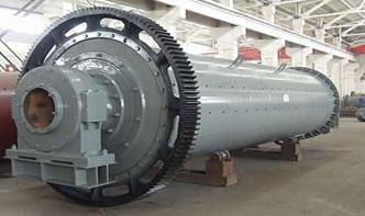
· Ball Mill Grinding Circuit. Even though many ores require fine grinding for maximum recovery, most ores liberate a large percentage of the minerals during the first pass through the grinding unit. Thus, if the free minerals can be immediately removed from the ball mill classifier circuit, there is little chance for overgrinding.

Electrician Circuit Drawings and Wiring Diagrams Youth Explore Trades Skills 3 Pictorial diagram: a diagram that represents the elements of a system using abstract, graphic drawings or realistic pictures. Schematic diagram: a diagram that uses lines to represent the .

Types of Circuits. Parallel Circuits Illustration. 2008 HowStuffWorks. A closed circuit has a complete path for current to flow. An open circuit doesn't, which means that it's not functional. If this is your first exposure to circuits, you might think that when a circuit is open, it's like an open door or gate that current can flow through. And ...
· Last updated at April 23, 2020 by Teachoo. Open circuit. Closed circuit. It is not a closed and continuous path. It is a closed and continuous path. Electric current doesn't flow in an open circuit. Electric current flows in a closed circuit. The key in an open circuit is shown as ( )

Multi Speed 3Phase Motor, 3 Speeds, 1 Direction – Power Control Diagrams; One line Diagram of Simple Contactor circuit. Three Phase Electrical Wiring Installation in Home – IEC NEC; How to Connect a Portable Generator to Home Supply System (Three Methods) A Simple Circuit Diagram of Contactor with Three Phase Motor. Resources:
Wiring diagram for standard MicroMark 7x14 mini lathe. XMT1135 LMS 2040: 2514: Wiring diagram for late model mini mill with red and yellow emergency stop switch. FC350BJ/110V LMS 1211: 3156: Wiring diagram for late model harbor freight mini lathe with illuminated rocker power switch and safety interlock circuit. FC250BJ/110V LMS 3149
My BP 1J Mill (on dealers floor)138kb. Milling Head Front View 1J 67kb. Milling Head Side View 1J 58kb. Power Feed (Original BP Type) 58kb. Powerfeed information 39kb Drawing #6 46kb. Longitudinal and Cross Feed Screw Information 56kb. 1J Parts List (H1 thru H271) 62kb. 1J Parts List (J1 thru M72) 98kb. Controls and Functions on "J" Type Head ...

DC Circuit Water Analogy This is an active graphic. Click any part of it for further details. In a direct current (DC) electrical circuit, the voltage (V in volts) is an expression of the available energy per unit charge which drives the electric current (I in amperes) around a closed circuit.
· This timer circuit uses a 555 IC timer. This is small, compact, and portable. 530 minutes timer. For the alarm by using the buzzer. We can select the time 5, 10, 15, and 30 minutes with S3 to S7 as the order. It makes clear the brain is ready to continue to work. Many friends like this.
· Schematic Diagram Circuit Diagram Is used in various industries, including but not limited to electrical engineering, buildings, constructions, chemistry, and etc. Is used only to illustrate how an electronic or electric circuit has to be prepared. Consists of industryspecific lines and symbols to illustrate the idea or concept.
result. Both circuits have the switch in series with the motor and supplied with electrical power when the switch is closed. The circuit shown in Figure is termed a ladder diagram. With such a diagram, the power supply for the circuits is always shown as two vertical .